Commutation sequence for BLDC motors
Introduction
This video from Maxon is probably the best introduction to the commutation of BLDC motors:
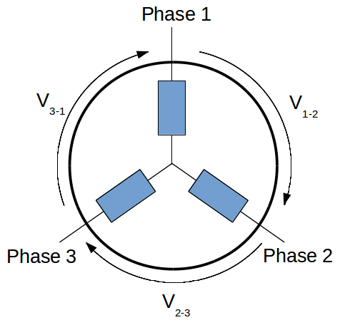
The following diagram shows a simplify overview of the BLDC motor controller. The motor inputs are the three phase and the motor provides as output the binary data from three hall effect position sensors. The phases are driven by three H-Bridge (usualy made of transistors but simplified here as switches). Each switch is driven by the microcontroller outputs (Q1H, Q1L, Q2H, Q2L, Q3H and Q3L). In the following we will assume that the switches are closed (on) when the signal from the microcontroller is high (for exemple QL1_bit=1 => QL1 is closed => Phase 1 is connected to the ground). In the same way, we will assume that the hall effect sensors are active high.

The following notation will be used for the windings voltage:
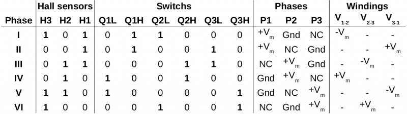
Clockwise commutation table
This table presents the commutation sequence for transistors, phases and winding according the hall effect sensors for the clockwise revolution.
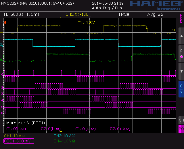
The following image is a BLDC motor signal oscilloscope capture. The yellow, blue and green ignals are the hall effect sensors respectively 1,2 and 3. The purple signals are the microcontroller output in the following order:
- 0 = GND
- 1 = Q1H
- 2 = Q1L
- 3 = Q2H
- 4 = Q2L
- 5 = Q3H
- 6 = Q3L

Counterclockwise commutation table
This table presents the commutation sequence for switchs, phases and winding according the hall effect sensors for the counterclockwise revolution.

Oscilloscope capture for the counterclockwize revolution (legend is the same as clockwise, see above):
See also
- Brushless Hall sensor frequency calculator
- Inside a Maxon EC45 BLDC motor
- MIT Motor GIM4310-36
- How to size a motor?
- Motor sizing for an autonomous mower
- Online motor sizing calculator