EAGLE Tutorial - Part 1 - Control panel
Introduction
In this tutorial, the reader will be guided to create a simple PCB. This page is the part 1 of the tutorial, dedicated to the control panel.
Eagle stands for Easily Applicable Graphical Layout Editor. It is an electronic CAD software manufactured by CadSoft Computer GmbH, a German company, since 1988. This software is provided with, among other, a schematic capture editor, a PCB (Printed Circuit Board) layout editor, an auto-router, a Computer-Aided Manufacturing (CAM)... It supports Windows, Linux and Mac OS X. This tutorial has been prepared with the following versions:
- EAGLE version 6.5.0
- Ubuntu 12.04 LTS
Control panel
When EAGLE is started, the following window appears on the screen,this is the control panel, the EAGLE starting window.
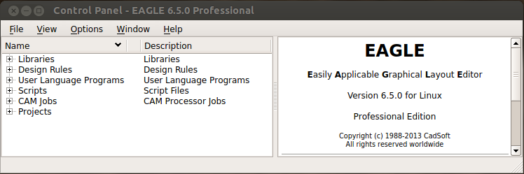
On the left hand side of the window the user manage existing and new projects and can get an overview about the libraries and settings:
- Libraries: this entry lists libraries of components, each component is composed of a schematic and a footprint linked together.
- Design Rules: the user can tune the parameters relevant to the board and its manufacture.
- User Language Programs: this is C-like programs that can be used for a variety of tasks. It can be used, for example, to modify your project and automize certain tasks.
- Scripts: the user can execute sequences of commands that are stored in a script file. It provides the ability to customize the program according to your own wishes (assign keys, load pc board shapes, change colors...)
- CAM Jobs: CAM stands for Computer-Aided Manufacturing. It generates output data for the manufacturing tools (for exemple exporting Gerbers files which is the most used professional format).
- Projects: this entry lists the examples and projets. When a new project is created, it is automaticaly added in the tree.
The Arduino MEGA2560 board has been designed with EAGLE. It is provided within the examples:

Directories
Basicaly, EAGLE stores all the projects and necessary files in the same main folder and creates subfolders to differenciate each projet. In the main menu bar, select Option > Directories:

The following interface allows the user to configure directories. $EAGLEDIR represents
the path to the main folder (on my installation it is located in /home/username/eagle-6.5.0/).
When a new project is created, a new folder is automatically added in $EAGLEDIR/projects/.
The user can specify several folders. It is possible, for example, to have the default
libraries available on a network server, and the personal projects in private local folders.
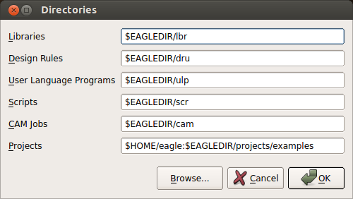
Before continuing check that the folder for libraries is configured with the following path:
$EAGLEDIR\lbrLibraries
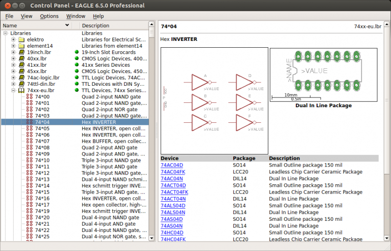
On the left hand side of the control panel, click on Libraries to develop the tree and select the library 74xx-eu.lbr. This library is dedicated to TTL Devices (74xx Series from Texas Instruments). Select a device, on the right side the symbol and footprint appear:
New project
To create a new project, select File > New > Project:

A new project is automatically added on the left hand side of the window under the branch Project/eagle. Enter you project name, for example FirstPCB:

Right click on the project and select New > Schematic:
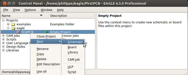
A new window is automatically open, this is the Schematic Editor:
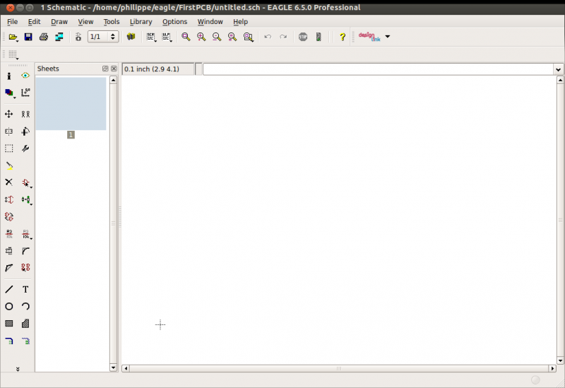
The part 2 of this tutotial explains step by step how to create your first schematics.
See also
- Adding copper pour in EAGLE
- Adding mounting holes to a PCB with EAGLE PCB software
- Create Solidworks 3D model from EAGLE
- EAGLE Tutorial - Part 2 - Schematic editor
- EAGLE Tutorial - Part 3 - Board editor
- EAGLE Tutorial
- Install EAGLE 6.6 on Ubuntu 16.04
- Understanding layers in EAGLE PCB Software
- Usefull EAGLE ULP scripts