Built-in RGB led on an ESP32 FireBeetle DFR0654
Introduction
This page explains how to configure and control the built-in RGB led on a the FireBeetle 2 ESP32-E IoT DFR0654.
This page has been done with the following versions:
- Ubuntu 22.04 LTS
- Arduino IDE 2.0.1
- ESP32 FireBeetle DFR0654
Built-in RGB led
In the schematics of the FireBeetle 2, there is a built-in RGB led on the board:
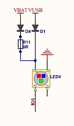
This RGB led is connected to the ESP32 pin IO5 (IO5/D8). You probably notice the LED has only one pin connected to the ESP32, while we need to drive the three colors (red, green and blue). The led is a WS2812. This led is designed to be cascaded:
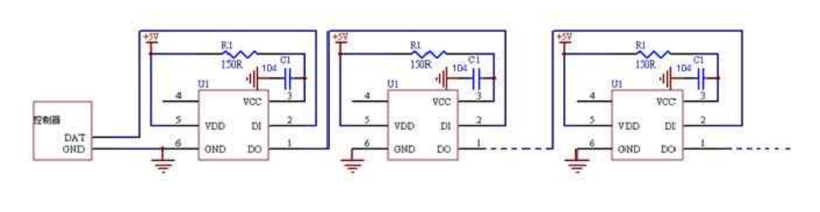
This explains why there is only one pin connected. The data is transmitted serially to each cascading led according to the following timeline:

FastLED library
Fortunatly, we don't have to write the code for controlling the RGB led. Daniel Garcia already did it for us. He wrote a library named FastLED. This library is designed to control WS2812 RGB leds.
If you are using the IDE Arduino, you can add download the library by selecting Tools > Manage Library. Search for the FastLED library and select the FastLED by Daniel Garcia:

To use the FastLED library, you have to include the library at the beginning of your code:
#include <FastLED.h>You also have to define the following parameters. The first one is the number of led connected:
// Only one led is connected
#define NUM_LEDS 1
The pin where the led is connected. As explain previously, in our case, the RGB led is connected to IO5:
// The led is connected on IO5
#define DATA_PIN 5
Since the library can control multiple cascading leds, we have to define an array of led. In our case, we just need one led. But to work, the library needs an array.
// Define an array of one leds
CRGB leds[NUM_LEDS];
Last step is to initialize the library and create a FastLED object. It can be done in the Arduino setup function:
void setup() {
  // Configure an array of (one) leds without SPI
  FastLED.addLeds<NEOPIXEL, DATA_PIN>(leds, NUM_LEDS);
}
This means there is a NUM_LEDS wire RGB led (NEOPIXEL) connected on pin DATA_PIN.
Controlling the RGB led
Basic (HTML) colors
Controlling the leds is quite easy. Just set the value of leds[0]. Several options
can be used. Specify color directly:
// Set the led red
leds[0] = CRGB::Red;
FastLED.show();
// Set the led green
leds[0] = CRGB::Green;
FastLED.show();// Set the led blue
leds[0] = CRGB::Blue;
FastLED.show();To send the command to the led, we have to call FastLED.show();. In the following,
this command is not repeated, but it has to be called to change the led color.
We can use any of the HTML / CSS standard color. Valid colors are listed on this page. For example, here the led is dark magenta:
// Set the led dark magenta
leds[0] = CRGB::DarkMagenta;
RGB
We can also set the three (red, green and blue) components:
leds[0].r = 220;
leds[0].g = 53;
leds[0].b = 65;
Or with the hexa code:
leds[0] = 0xDC3545;Or with the setRGB() member function:
leds[0].setRGB(220, 53, 65);HSV
We can also set the HSV values (between 0 and 255):
leds[0] = CHSV( 251, 194, 255);With the alternative member function:
leds[i].setHSV( 251, 194, 255);Source code
Here is the source code of the rainbow sequence presented in the introduction video:
#include <FastLED.h>

// Only one led is connected
#define NUM_LEDS 1

// The led is connected on IO5
#define DATA_PIN 5

// Define an array of one leds
CRGB leds[NUM_LEDS];

void setup() {
  // Add array leds without SPI
  FastLED.addLeds<NEOPIXEL, DATA_PIN>(leds, NUM_LEDS);
}

void loop() {
  // Loop through rainbow colors
  for (int i=0; i<=255;i++) {
    leds[0] = CHSV( i, 255, 100);
    FastLED.show();
    delay(16);
  }
}
Download
See also
- How to install ESP32 boards in the Aduino IDE?
- Linearity of the ESP32 ADC
- ESP32-DevKitC V4 real current consumption in deep sleep mode
- ESP32 FireBeetle DFR0478 real current consumption in deep sleep mode
- ESP32 FireBeetle DFR0654 real current consumption in deep sleep mode
- ESP32-S3-DevKitM-1 real current consumption in deep sleep mode
- ESP32 real current consumption in deep sleep mode