Customer tele-information on French electric meter Linky
The Linky electric meter, intended to be installed in all French households is equipped a digital tele-information output, commonly called TIC (Télé-Information Client / customer tele-informaiton).
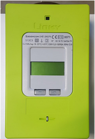
This gives the customer the opportunity to get in real time their electrical consumption. It continuously broadcasts the parameters updated by the counter. The output is of the classical asynchronous type and the information is transmitted in series on the line. The TIC connector is in the lower corner meter right. Note that this output is purely informative and the information transmitted have no contractual value.

Power supply
The TIC output has a power supply (at 50 kHz) which supplies power to the receiver. The TIC power supply circuit is on pins I1 and A. This pins can be used by customers to power a tele-information receiver attached to the meter (a radio module for example).

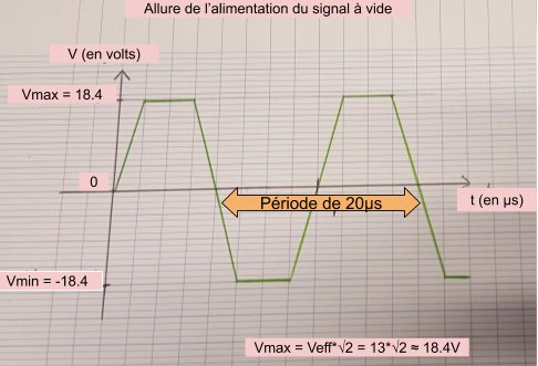
No load specification
Without load on power supply (no current consumed), the voltage across the terminals of power is about 13 Vrms max.

Specification with load
To respect the characteristics below, the Linky are tested on purely resistive loads between 225 and 335 ohms; the aim being that the guaranteed power is always greater than 130 mW.
| Specification | Value |
|---|---|
| Power provided | min. 130 mW |
| Voltage | 6Vrms +/- 10% (max 12V peak) |
| Frequency | 50kHz |
The two most used converted output voltage values are 3.3V and 5V. With 130mW of minimum power supplied, the output currents are respectively about 39.4mA and 26mA.
Data transmission
Data transmision is sent on pins I1 and I2. The signals can be transmitted over a wired bus (serial link modulated on twisted pair). To have efficient operation and respect the electrical characteristics, the maximum length of the line must not exceed 500m.

Customer tele-information can be configured in two modes:
- Historic mode : in this mode, the Linky meter makes it possible to restore information frames equivalent to those of the old electronic counters (1200 baud or 1 bit every 833us)..
- Standard mode : this new mode appeared with Linky meters. It is faster than the historical mode, and contains many information, with a specific formatting (9600 baud is 1 bit every 104us).
The information signals are of the “amplitude modulation” type on a carrier at 50 kHz as illustrated below:

- Blue: the shape of the information signal amplitude modulated at 50 kHz (output from the TIC)
- Pink: the shape of the demodulated and inverted signal (the combinational logic is negative), output from the optocoupler
- Green: the shape of the signal ready to be processed (demodulated and inverted)
Historic mode specifications
| Specification | Value |
|---|---|
| Transmission | Binary with a carrier modulated at 50kHz |
| Carrier frequency | 50kHz |
| Unidirectional | From meter to receiver |
| Transmission rate | 1200 bauds |
| Time for one bit | 833 us per bit |
| Coding logic | Negative : if the carrier is present, the bit is 0, otherwise 1 |
| Parity | Even |
| Data bits | 7 bits (ASCII) |
| Stop bit | 1 bit |
Standard mode specification
| Specification | Value |
|---|---|
| Transmission | Binary with a carrier modulated at 50kHz |
| Carrier frequency | 50kHz |
| Unidirectional | From meter to receiver |
| Transmissionr ate | 9600 bauds |
| Time for one bit | 104 us per bit |
| Coding logic | Negative : if the carrier is present, the bit is 0, otherwise 1 |
| Parity | Even |
| Data bits | 7 bits (ASCII) |
| Stop bit | 1 bit |
Transmission
Physical layer
Les caractères sont émis sur 10 bits dont la composition est la suivante :
- un bit de start avec un
0logique - sept bits pour représenter le caractère en ASCII
- un bit de parité avec une parité paire
- un bit de stop avec un
1logique

Bits are transmitted from LSB (Least Significant bit) to MSB (Most Significant bit).
Data link layer
Frames are transmitted continuously. These are composed an STX character (0x02) indicating the start of the frame, followed by the frame content composed of several characters and a final ETX character (0x03) indicating the end of the frame.

Historic mode
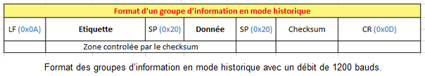
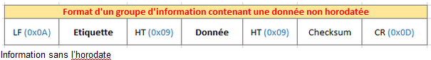
In each line there is information sent by the meter. Each piece of information is perfectly delimited in order to be able to parse frames easily. This begins with a Line Feed which indicates the beginning , a label, a space, the data field, a new space, the checksum and a carriage return which indicates the end of this line.
Standard mode
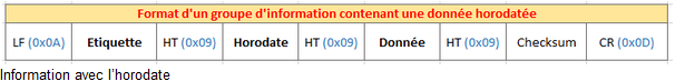
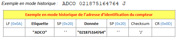
Transmitted data is preceded by a label allowing to identify it (for example: ADCO is the label for the "Meter address"). Information groups can be made up of 7 to 9 parts (depending of the timestamp), a start character (line feed), a label, several separators (horizontal tab), the data, a checksum, and a closing character (carriage return).
Example in historic mode: ADCO 021875164764
Application layer
The detail of the application layer is very well explained in chapter 6 of the documentation provided by Enedis.
Sources and references
- Sorties de télé-information client des appareils de comptage Linky utilisés en généralisation par Enedis
- Avec n’importe quel microcontrôleur,cette carte récupère l’alimentation fournie par la TIC.
- Utilisation d’une Raspberry Pi