Introduction to LoRa32 V2.1_1.6 Point-to-Point Communication

Introduction
The LoRa32 V2.1_1.6 is a compact and powerful development board based on the ESP32 microcontroller, integrated with a LoRa (Long Range) transceiver module, typically the SX1276 or SX1278. This combination enables long-range, low-power wireless communication, making the board an ideal choice for Internet of Things (IoT) applications, remote sensing, and embedded projects. One of the fundamental modes of communication supported by these devices is point-to-point (P2P) communication, where two LoRa modules communicate directly without the need for any gateway, router, or central network infrastructure.
Point-to-point communication with LoRa32 V2.1_1.6 involves configuring one device as a transmitter and another as a receiver. This setup allows reliable data transfer over long distances (often exceeding several kilometers in open environments), while consuming minimal power—perfect for scenarios like rural monitoring, remote controls, and ad-hoc wireless links.
This document (or guide) will explore how to set up and implement point-to-point communication using LoRa32 V2.1_1.6 modules, including hardware requirements, software setup using the Arduino IDE, and example code to establish and test basic data exchange between two nodes.
These tutorial has been tested with the following versions:
- LoRa32 V2.1_1.6
- Ubuntu 24.04 LTS
- Arduino IDE 2.3.6
- LoRa library v.0.8.0
IDE Configuration
If not done yet, install the Arduino IDE.
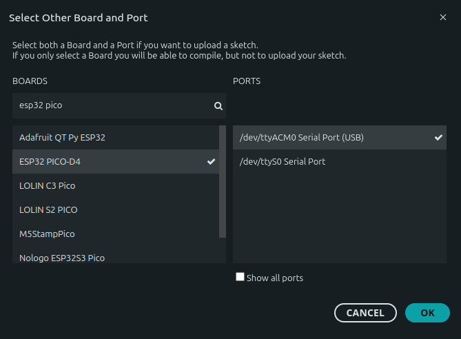
The Lora32 V2.1_1.6 is based on the ESP32 Pico D4. Select this generic board in the Arduino IDE :
Install the LoRa library :

Sender Code
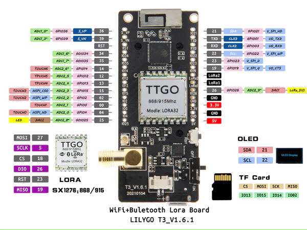
The first ESP32 will be configured as sender. The HF transmiter is connected through the SPI port. We first need to configure the SPI pins connected to the transceiver module. This configuration is bases on the pin diagram provided by the manufacturer :
When initializing the LoRa library, we have to specify the frequency :
433E6for Asia (433 MHz)866E6for Europe (868 MHz)915E6for North America (915 MHz)
Here is the full code:
#include <SPI.h>
#include <LoRa.h>

int counter = 0;

// Define the pins used by the transceiver module
#define SCK 5
#define MISO 19
#define MOSI 27
#define SS 18
#define RST 23
#define DIO0 26

void setup() {
  Serial.begin(115200);
  while (!Serial);

  Serial.println("LoRa Sender");

  // Configure SPI pins
  SPI.begin(SCK, MISO, MOSI, SS);

  // Setup the transceiver
  LoRa.setPins(SS, RST, DIO0);

  //433E6 for Asia (433 MHz)
  //866E6 for Europe (868 MHz)
  //915E6 for North America (915 MHz)
  if (!LoRa.begin(866E6)) {
    Serial.println("Starting LoRa failed!");
    while (1);
  }
}

void loop() {
  Serial.print("Sending packet: ");
  Serial.println(counter);

  // send packet
  LoRa.beginPacket();
  LoRa.print("Packet #");
  LoRa.print(counter);
  LoRa.endPacket();

  counter++;

  delay(5000);
}
Once the ESP32 is programmed, you may have to reset the module by pressing the reset button to start the program. You should see something like this in the Arduino monitor:
LoRa Sender
Sending packet: 0
Sending packet: 1
Sending packet: 2
The LoRa module sends a packet every 5 seconds.
Receiver Code
The receiver code is very closed to the sender, but it loop until LoRa data are available and display the received data in the monitor :
#include <SPI.h>
#include <LoRa.h>

// Define the pins used by the transceiver module
#define SCK 5
#define MISO 19
#define MOSI 27
#define SS 18
#define RST 23
#define DIO0 26

void setup() {
  Serial.begin(115200);
  while (!Serial);

    Serial.println("LoRa Receiver");

  // Configure SPI pins
  SPI.begin(SCK, MISO, MOSI, SS);

  // Setup the transceiver
  LoRa.setPins(SS, RST, DIO0);

  //433E6 for Asia (433 MHz)
  //866E6 for Europe (868 MHz)
  //915E6 for North America (915 MHz)
  if (!LoRa.begin(866E6)) {
    Serial.println("Starting LoRa failed!");
    while (1);
  }
}

void loop() {
  // try to parse packet
  int packetSize = LoRa.parsePacket();
  if (packetSize) {
    // received a packet
    Serial.print("Received : '");

    // read packet
    while (LoRa.available()) {
      Serial.print((char)LoRa.read());
    }

    // print RSSI of packet
    Serial.print("' with RSSI ");
    Serial.println(LoRa.packetRssi());
  }
}
Once both codes are launched, you should see on receiver side something like:
LoRa Receiver
Received : 'Packet #4' with RSSI -5
Received : 'Packet #5' with RSSI -5
Received : 'Packet #6' with RSSI -4
Received : 'Packet #7' with RSSI -5
Received : 'Packet #8' with RSSI -15
Received : 'Packet #9' with RSSI -5
RSSI means Received Signal Strength Indicator is a measurement of the power level (signal strength) that the receiver detects. The higher is the best.
Conclusion
The LoRa32 V2.1_1.6 development boards provide a simple yet effective way to implement point-to-point (P2P) long-range communication using the LoRa protocol. By following the setup and example code provided in this guide, you can easily establish a reliable data link between two devices—without requiring any intermediate infrastructure like a gateway or server.
With proper SPI pin configuration and frequency selection based on your region, the boards can exchange messages over several kilometers with minimal power consumption. This makes them ideal for applications such as environmental monitoring, remote control systems, and custom IoT deployments where network independence and long-distance communication are essential.
Now that you’ve successfully built a basic sender-receiver LoRa setup, you can expand the system with encryption, acknowledgments, mesh networking, or sensor integration for more advanced and secure projects.
Downloads
See also
- Change A31301 I²C address via EEPROM
- Connector MR30
- Datasheet for the AZDelivery Display SSD1306
- Hall effect sensor Allegro A31301
- Farad to watt.hour capacity converter
- Online resistance calculator